

The problem #
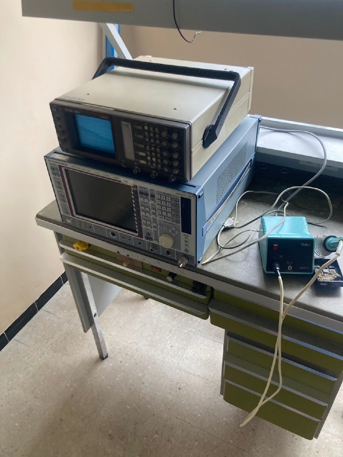
When I got the spectrum from my last university, it was kind of functional.
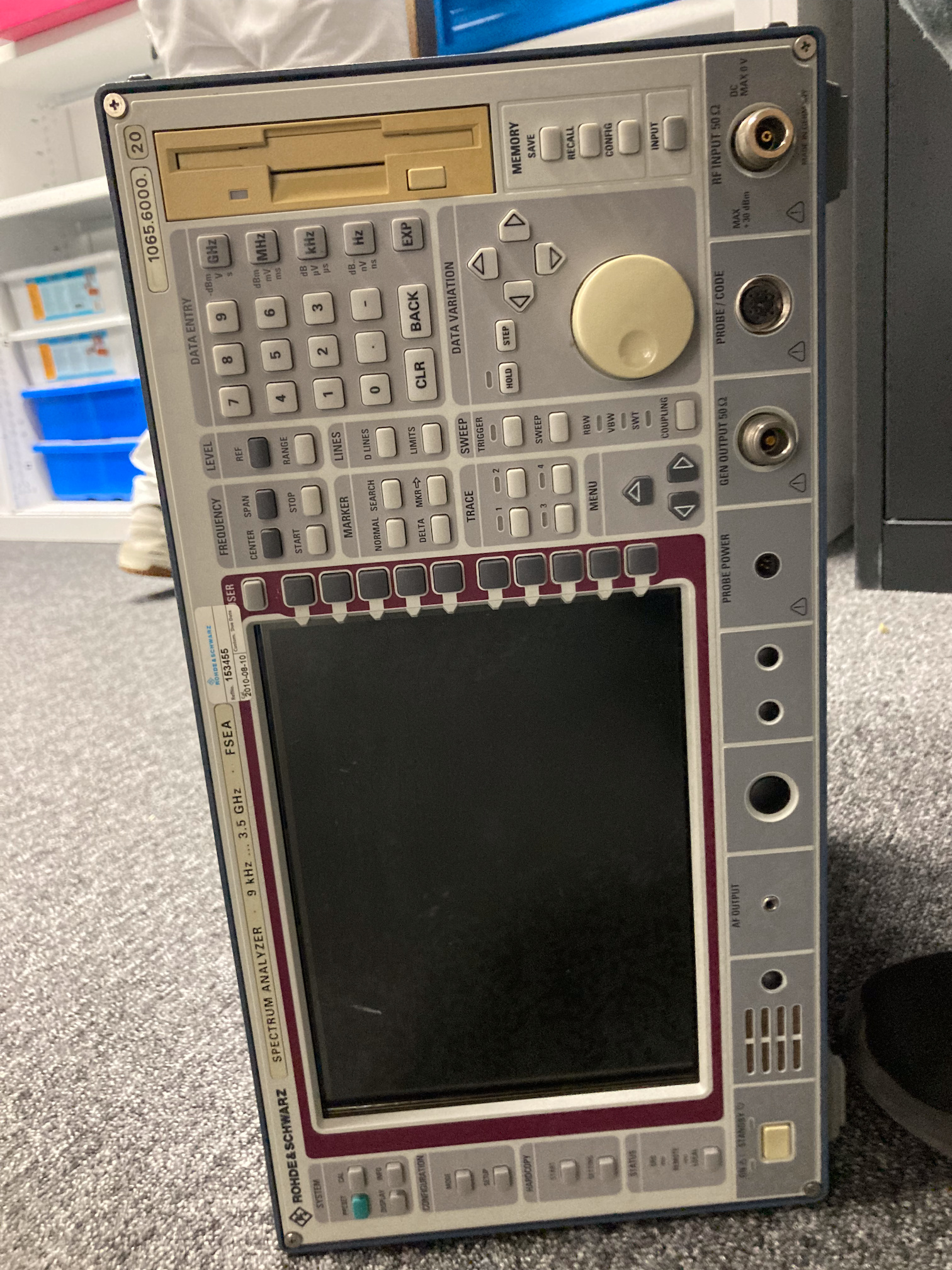
By this I mean that it turned on, but it almost never actually booted to Windows. It showed a screen of the booting process, showing the booting of all the analog modules and ensuring that the transputers were booted.
Transputers are akin to GPUs we have today; they function as separate computers on dedicated boards, designed to perform parallel calculations.
When it finished booting all the internal peripherals, it attempted to start Windows (in this case Windows NT). This only worked if you restarted immediately after everything had booted, without disconnecting power. What was observed was that the hard drive almost always stopped spinning, halting the boot process.
Having a failing drive in such a device is problematic, because even after contacting Rohde & Schwarz I had no way of recovering the software for this machine.
Hail Mary #
So here comes the hail‑mary plan. I found out that on EEVBlog there was someone who attempted the same feat; it was also the only information available online about it.
This is the project: EEVBlog (if it’s no longer available, copy the link to the Wayback Machine; I’ve backed it up just in case).
In their instance, they were working with a slightly different machine, the PC card differed, and the hard drive was mounted on it.
Teardown #
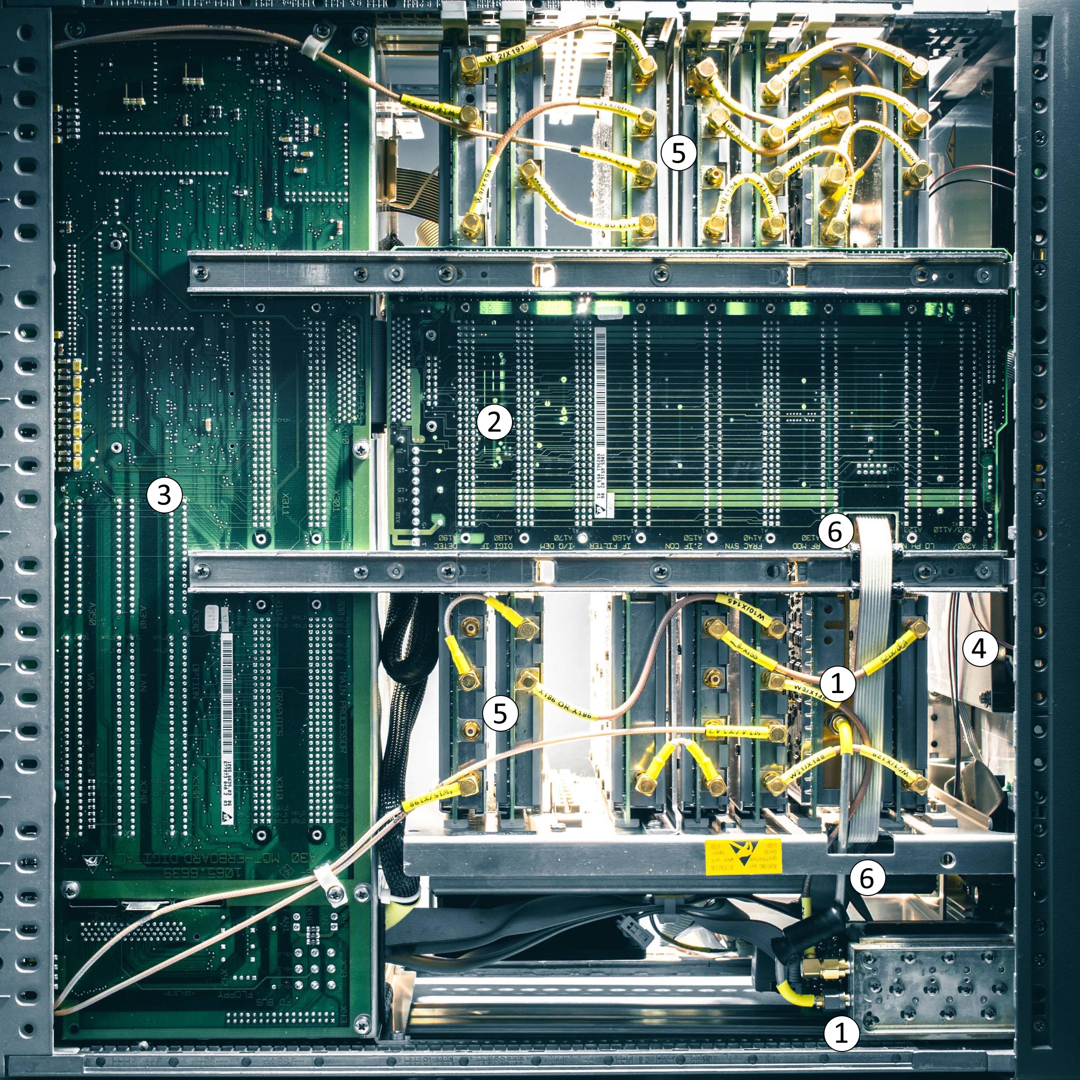
All credit goes to Muxr on EEVBlog for this image.
| Nr. | Name |
|---|---|
| 1 | Input oven, with aluminium tube coaxial cable |
| 2 | Digital data bus for the analog modules |
| 3 | PC board, with expansion slots, IDE connector |
| 4 | Front display and button assembly |
| 5 | Analog modules, connect via coaxial |
| 6 | Data for input oven, and range selection |
On these images we can see the backplane (2). It is surrounded by aluminium locking rails and connectors on the other side, with a digital communication bus. This bus then connects to the PC board (3). You can see all the analog boards connected to the bus (5) via gold‑plated copper coaxial cables, which are labeled wonderfully, thanks R&S.
The back of the device shows the input filter box on the bottom right (1), where the main input is situated. When turning this over, we can see the PC board. The PC board consists of a mainboard with two large sockets where the PC and its RAM live.
The other card contains the transputers and its RAM.
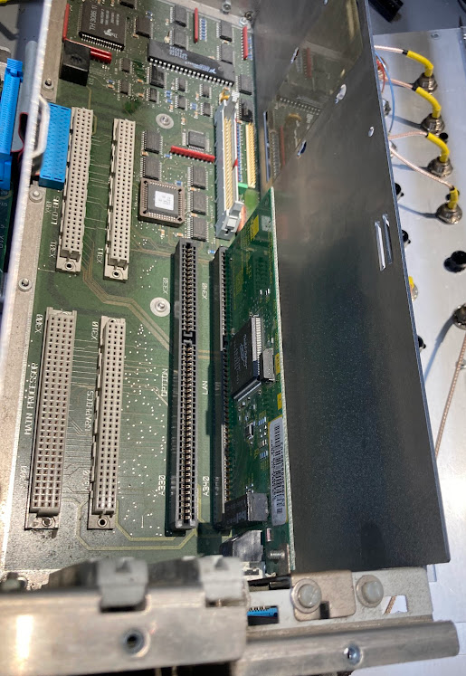
The PC and transputer cards plug into the white sockets. In this image you can also see the drive mount and the IDE and CF sockets for the drive. I even installed an ISA network card for fun.
Hard drive #
So now that it’s open, I first want a clone image of the hard disk so that if I lose the hard disk or something else happens, I have a backup. These old drives are getting rare and fragile, so having a raw image is essential.
I connected it to a CF drive reader (do not use generic CF card readers, as there are a couple of generations that use the same 50‑pin connector but are not electrically or logically identical). Early CF cards were designed to be backwards compatible with IDE/ATA (True IDE mode), meaning they could behave almost exactly like a normal hard disk. This is why they are often used as drop‑in replacements in older systems.
However, modern CF cards are a bit different internally. While they still can support True IDE mode, many newer ones prioritize memory‑mapped I/O mode or rely on more modern ATA features (like LBA‑only access, different timing expectations, or power‑up behavior). Some even depend on controllers that expect a more modern host and don’t properly fall back to the simpler legacy modes.
On top of that, CF card readers (especially USB ones) often abstract everything away and expose the card as a generic mass storage device, completely hiding the low‑level ATA interface. That means you’re no longer talking directly to the device in the same way an old system would, which can cause subtle incompatibilities or prevent proper cloning.
I connected it to a Unix system (in this case an old 2013 MacBook Pro) and did a terminal copy using dd to copy the drive to an image. This does a sector‑by‑sector copy, so it preserves everything exactly as‑is, including boot sectors, filesystem quirks, and any odd partition layouts.
This is what the original drive looks like:
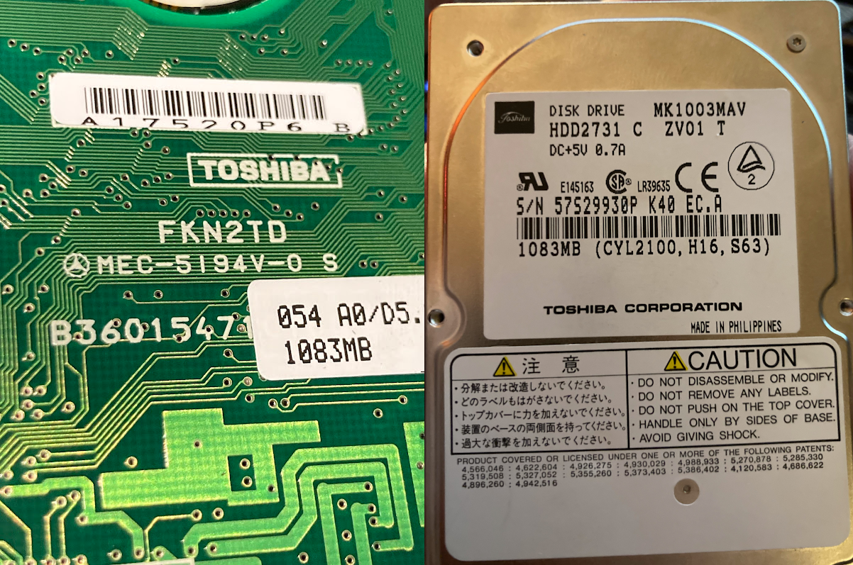
It is a 1 GB drive made by Toshiba. The drive on the back has a Mercedes‑like logo (probably just the manufacturer’s mark, but it really does look like one).
Once copied to a hard disk, I loaded up an older CF card (newer ones don’t work because of the generation mismatch), in this case 2 GB, and again used dd to copy back the image file to this card. The size mismatch is fine here since the image is smaller than the target, but anything larger would obviously not fit. Also worth noting that some older systems are picky about CHS/LBA translation, so even if the size fits, geometry differences can sometimes cause issues.
I then plugged the PC card and the transputer card in, and inserted the CF card.
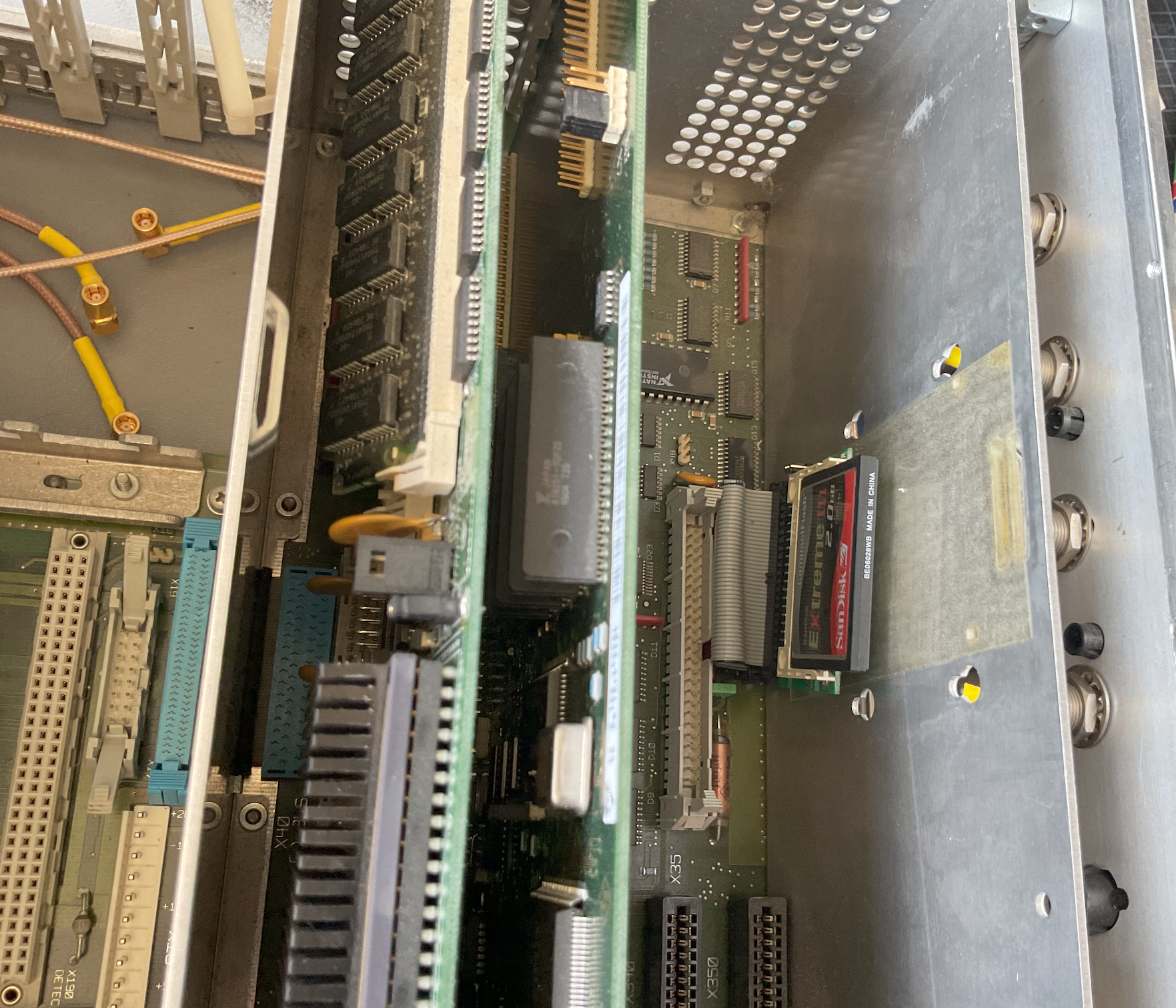
It looks like an Intel i486 CPU. My guess is that it’s a 486 DX or DX2, but the heatsink is glued so I won’t tear it down.
And hurrah, we have life!
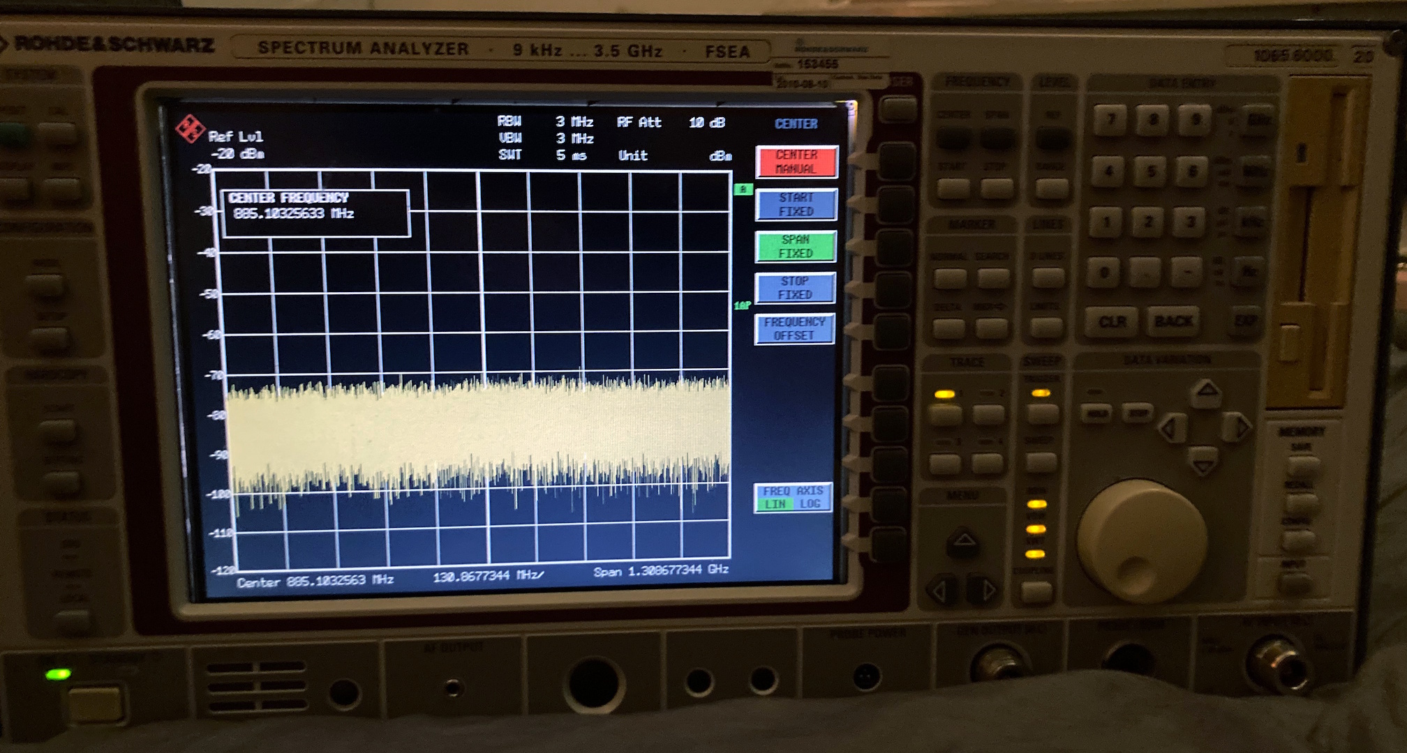
I still need to figure out how this machine works. A future project could involve trying some RF filters, attaching antennas, and performing spectral analysis.